Flow Control Valve Chamber
Mechanical Design & BIM Modeling
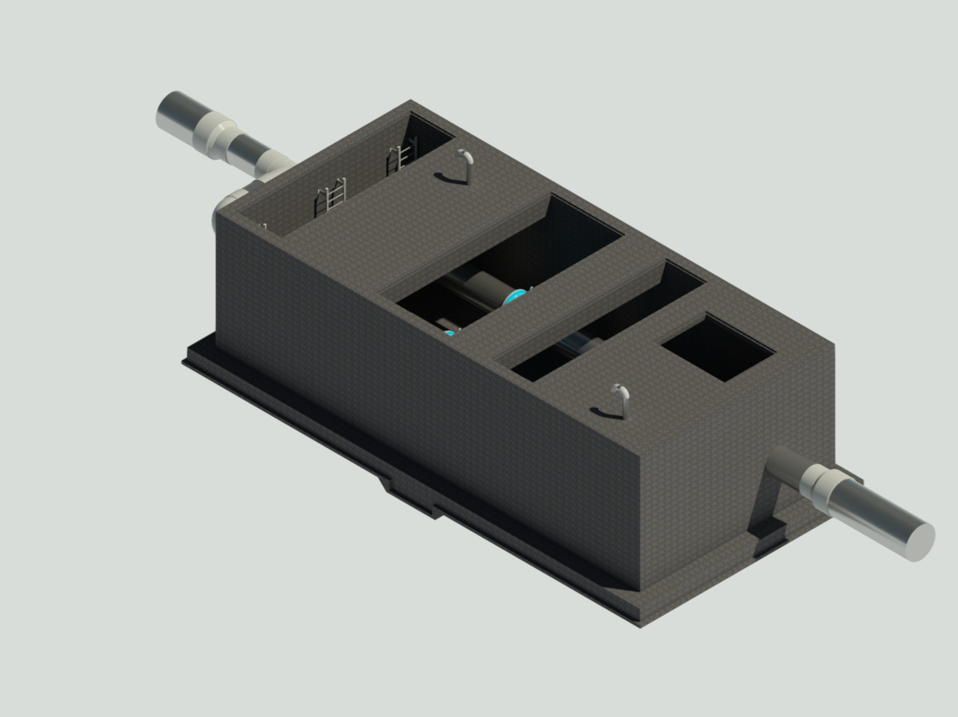
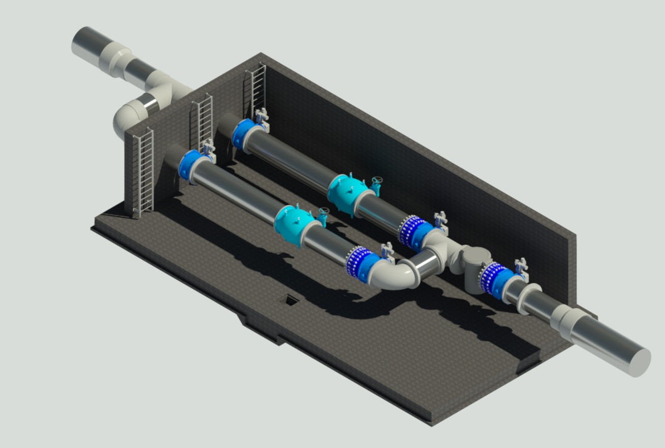
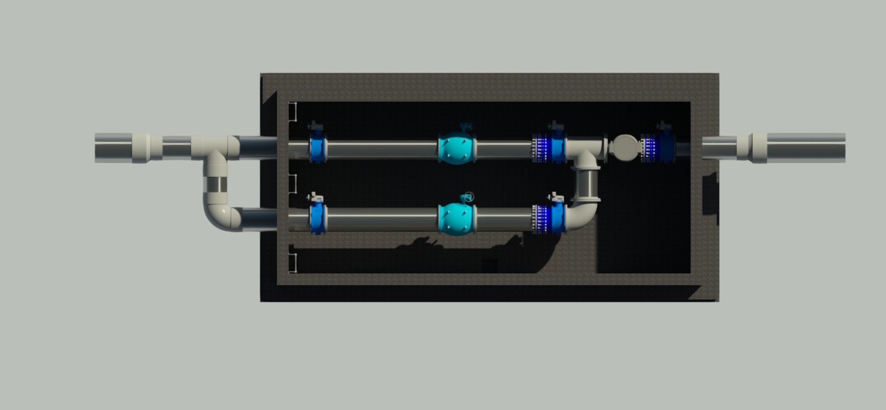
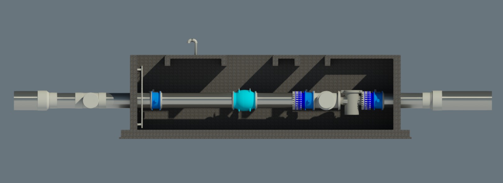
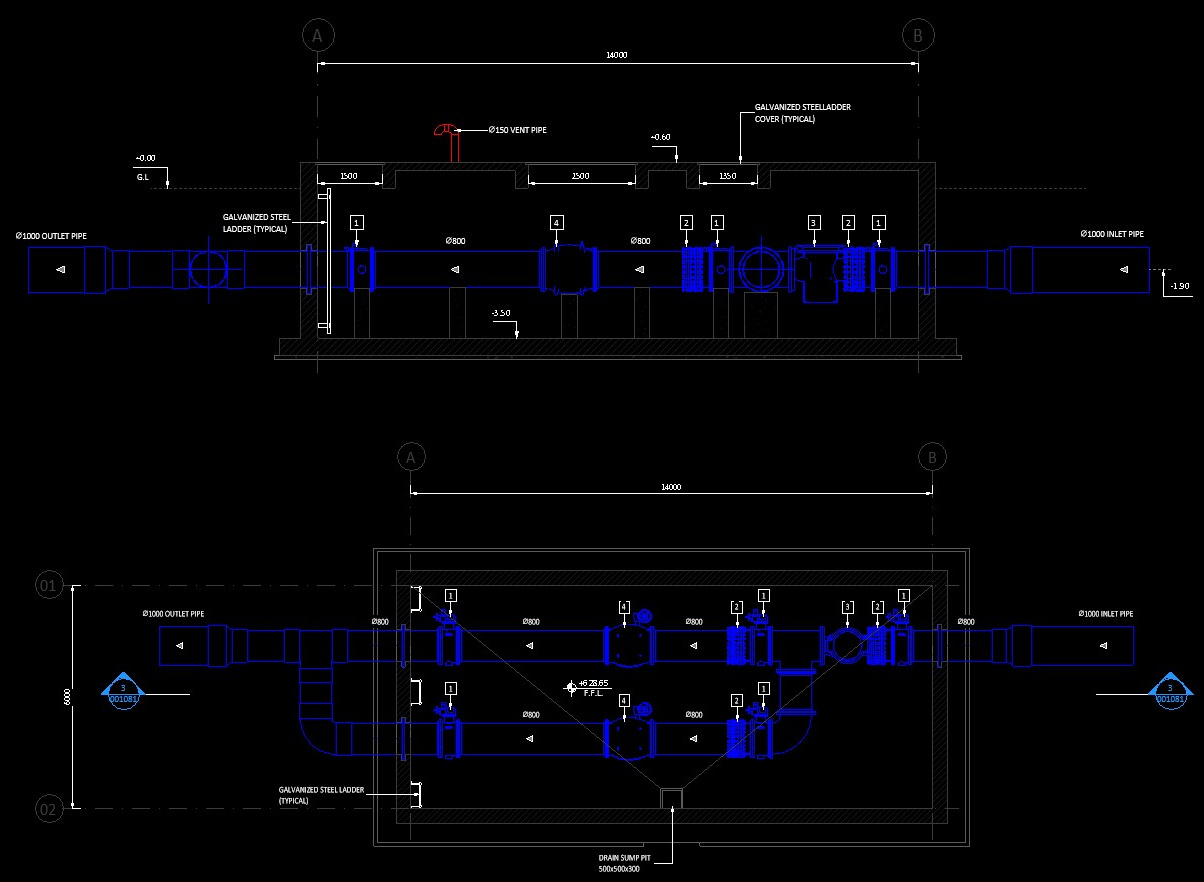
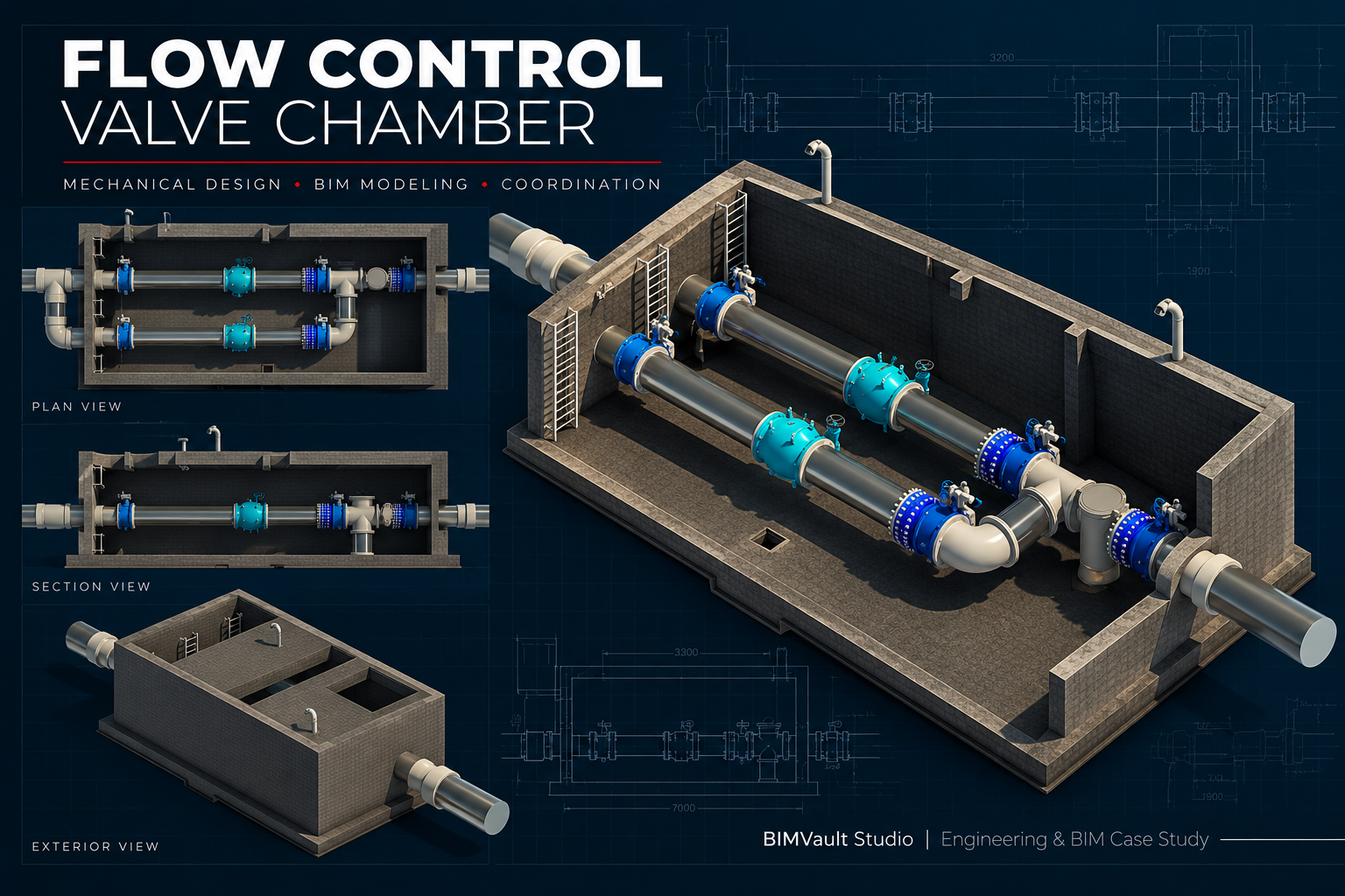
A dedicated Flow Control Valve Chamber designed to accommodate major pipeline and valve assemblies within a coordinated mechanical and BIM environment. The layout integrates parallel flow-control arrangements, access provisions, ventilation, drainage, and maintenance considerations within a compact underground chamber.
What was delivered
Mechanical design and BIM modeling of a Flow Control Valve Chamber, including pipeline and valve arrangement, mechanical equipment layout, access provisions, drainage and ventilation coordination, and multidisciplinary BIM coordination.
Selected Technical Parameters
Engineering Verification
Mechanical design verification focused on the hydraulic and physical arrangement of the valve chamber, including pipeline alignment, valve and fitting coordination, access and maintenance provisions, ventilation, drainage, and level relationships. The BIM model was developed to verify spatial coordination, constructability, and clear access to the mechanical assemblies within the chamber.
Selected Project Views